Most Effective Ways To learn Printed Circuit Board Fabrication
Table of Contents:
1. Introduction printed circuit board fabrication
2.Milling
3.Fabrication Flow of PCB
4.Circuit PCB board design in Eagle
5.Package selection guideline
6.Creating Custom Parts in printed circuit board fabrication
7.Generating a PCB Layout
8.CAD file preparation in CircuitCAM
9.Printed Circuit Board Fabrication insulation of pins and traces
10.PCB circuit board quick reference sheet
Introduction
Printed Circuit Board Fabrication is a useful guide that will help printed circuit board manufacturers to design a PCB fabrication. In addition, in many cases, making circuits by hand is not possible or practicable. This PCB circuit board design guide is a low cost and rapid facility to make two-sided PCB.
Milling - Printed Circuit Board Fabrication
Q. What is the photolithographic process of Printed Circuit Board Fabrication?
There are several methods that describe the manufacturing of printed circuit pcb boards. The most common method which is used commercially to manufacture PCB is a photolithographic process.
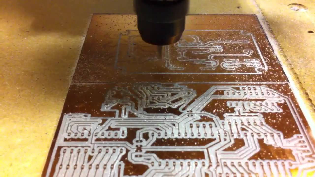
It is defined as a process that uses light and rays to remove thin particles. Similarly, in milling, it removes the insecure or unwanted copper from the copper substrate. It is a mechanical process that prepares the PCB circuit board to be printed.
Q. What is milling in printed circuit board fabrication?
It is a major step in printed circuit board fabrication. Furthermore, a pcb board manufacturer removes extra copper. This whole process requires mechanical skill. Because a minor mistake can damage circuit pcb board design.
NOTE: The boards formed by milling are referred to as PCB”
Fabrication Flow of PCB -Printed Circuit Board Fabrication
CAD design
There is a variety of CAD design packages. It consists of three different software packages for Printed Circuit Board Fabrication.
The following sections in the article will describe the CAD flow. Eagle PCB circuit board was selected for this purpose.
Q. What are the benefits of Eagle printed circuit board fabrication?
Eagle has following Printed Circuit Board Fabrication benefits:
- It is available on all major windows platform including mac os
- Have a lot of features (auto-router tool, DRC etc.)
- It is a good file for predefined pats and footprints
- Maintain the connection between Layout and Software.
Circuit PCB board design in Eagle
This portion has the information in detail for Eagle users. Simultaneously, a user must have basic information about the functions of Eagle Printed Circuit Board Fabrication. Before starting the process of the printed circuit PCB board, the design of the circuit must be complete. Why it is important for printed circuit board fabrication? Because guessing and applying the wrong components may lead to a waste of money and time.
How does printed circuit board fabrication involves Schematic?
This section describes the basic instruction for your project, for creating a schematic. A printed circuit board fabrication manufacturer should heed to these points and directions. In short, it will help him in printed circuit board fabrication.
Package selection guideline
The selection of a better package is necessary. The important dimension package is pin “pitch”
Pin pitch
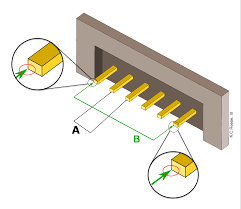
The separation between the centers of the pins is pin “pitch”. 0.5mm is a perfect milled space. Subsequently, It is difficult to handle it manually in making a printed circuit pcb board.
DIP packages are very useful in printed circuit board fabrication. They carry a vast space to complete the required steps.
Creating Custom Parts in printed circuit board fabrication
Q. Why is there a need for creating parts in Eagle?
There is a collection of parts in default libraries of Eagle but some parts may not exist. In such a case, pcb board manufacturer must create parts.
The difficulty faced while customizing parts
Defining a package footprint is the time taken of customizing parts.
Solution
The most time-consuming part is defining the footprint, in such a case a user can re-use the already formed footprint from the library.
Q. instructions and steps to define a custom device?
These are the instructions that describe the custom PCB circuit board device in Eagle step by step.
- Create an Eagledevice library first.
- Packages are almost predefined, instead of making a new one paste the existing part in the library.
- Similarly, Save the package, on the library window click Symboland create a new symbol.
- Do not forget to make a schematic design and later save it.
- In the Library window click Device and create a new device. A custom device can be created.
- In the window, click Add and to present the customize symbol
- Click Newand link the desired package.
- Click Connect, symbol and package pins connect. This step must be performed carefully.
Generating a PCB Layout
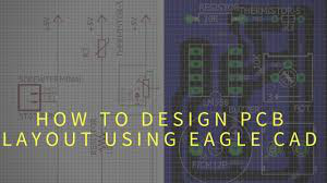
This part of Printed Circuit Board Fabrication explains the equipment a circuit PCB board manufacturer uses in PCB fabrication.
Pcb fabrication routing restrictions
Plated VIAs are in the process because of Eagle. But it is not available for the LPKF machine. The VIAs connect the traces through the pins from both the layers.
The plated VIAs route the holes from both sides which mat block the top layer while processing. Thus, in Eagle it the responsibility of the user to make sure the PCB fabrication process is smooth.
How to Make a Printed Circuit Board Fabrication Ground plane?
A fiberglass substrate is sandwiched between the top and bottom layers of copper, in a typical two-layered PCB circuit board. Subsequently, both layers are connected to the ground node.
Q. What are the uses of the Ground plane?
It has the ability to enhance the executing power of analog design. Avoid unwanted ground noise.
Q. How to avoid unwanted Ground noise during PCB fabrication?
Printed Circuit Board Fabrication manufacturers use a new technique to minimize ground noise on the PCB circuit board. It is called a low resistance ground.
Steps
- Leave the eagle-routed and connect the pin to the ground plane (additional step is there in Circuit CAM)
- Enter the command rip-up and in the command line to unroute the ground node
- The pins are now connected to the yellow “air wires”
Pcb fabrication involves various layers. Similarly, it reduces distance. But make it sure that if you are generating more layers, it must be equal and fixed on all sides.
PCB example
The simple circuit consists of
- Two surface-mount IC’s
- Passive components
- Connectors
- Two DIP switches
“Note- left the ground pins un-routed”
Exporting to CircuitCAM
Q. How Eagle design transfer to CircuitCAM?
Some files are there which can be used to transfer the Eagle design to CircuitCAM completely.
Q. What does the export file contains by Eagle PCB circuit board?
- Does not contains connectivity information
- Contains the desired traces for the layers
- Contains required drilling diameter
CAD file preparation in Circuit CAM
Q. What are the uses of Circuit CAM?
Circuit CAM is used to
- to insulating layers to traces
- to integrate copied files of eagle system
- and at the end to make design for milling process
Q. Write the procedure in steps to prepare CAD files in CircuitCAM.
Following are the steps:
- Open CircuitCAM
- Select File > New
- Click wizard icon, wizard window will open
- Click next, choose a sol, file for the bottom layer is selected.
- Select YES and click next, if the file looks correct.
- It shows the layers overlapped correctly then click next.
- Select “NC-drill file” by selecting drd. Click Next.
Printed Circuit Board Fabrication insulation of pins and traces
Why there is a need?
LPKF machine is used insulation lines to mill around printed circuit pcb board traces to avoid the traces being shorted to the ground plane. Furthermore, to automate the insulation CircuitCAM uses a built-in algorithm. Moreover, by using counter board PCB and copper board are separated.
Instructions
Following are the instruction for PCB board insulation:
- From Gerber directory Click File > Import > board.otl
- Then use the default setting (recognizing “board Outline” layers) and tap Import
- Choose edit > contour routing
- Around the border, a counter routing layer will create by default
- Select edit > insulate
- Keep the default setting, select bottom layer and click Run
After the process complete, repeat procedure 5-6. But focus on the top layer. After that, it displays the board traces.
Now remove the insulation from the pins. All four layers must be deleted one by one by selecting them. Two layers are invisible until they are selected and the other two are of surface mount-pads. Repeat step 8 for each pin
Printed Circuit Pcb Board Rub-out regions
Q. What is a PCB fabrication Rub out the region and what is its purpose?
Printed Circuit Board Fabrication rub out region allows the process easier as it is the region around the pitch. During soldering, pin to the ground plane may be short. In addition, to avoid such an accident rub-out region is used. Unnecessary rubbing can damage the bit also.
PCB fabrication using BoardMaster
To start PCB fabrication here are some steps, copper boards are made by the design centers and given to the students. The boards are cleaned and already drilled.
Q. How to adjust the drilling depth?
To adjust the depth an instrument known as the height adjustment screw is used. The depth is adjusted not to damage the platform of printed circuit board fabrication. Subsequently, to adjust the intensity Printed Circuit Board Fabrication manufacturers use a
- test copper sheet on the head of the drill
- Place adjustment screw,
- the depth is appropriate when the bit barely touches bellow the test board
Calibrate Pcb Fabrication Milling depth
Q. Steps to calibrate milling depth for printed circuit board fabrication
- Load the universal milling bit, from Exchange location
- Adjust the height so the bit does not touch the drill head
Q. Why there is a need to adjust depth?
Adjustment of high of bit important, if it is deep and touches the drill head it will destroy the milling bit.
Q. How to adjust milling depth in the PCB circuit board?
In the whole process adjustment of depth is most difficult and challenging. Thus, it must be held by hand.
Isolation groove is deep; copper lines may be milled away because they are closely placed
Q. Follow the steps to properly determine the depth.
There are the following steps
- Place the milling head to the corner of the copper board.
- Use command move 40 mm in the y-direction to verify the depth.
- After the verification, pull down the head to forty meters.
- Repeat his step until you have adequate depth.
Drilling phase Printed Circuit Pcb Board
Q. Write the steps of the drilling phase
Following are the steps
- Position the drill head on the Exchangeposition and tape the board to secure it before starting the process.
- Now place the board accurately and check whether the drill head and edges of the board are aligned and coordinated. This is necessary for the milling process for milling many times in a single session.
- You must adjust the drilling depth as told before, to load the bits
Follow the steps to drill all the holes, if the appropriate size of diameter is not available then try the other smallest bit to drill accurate holes
Milling PCB board layers for PCB fabrication
Q. steps of printed circuit board fabrication Milling
After adjusting the milling height, follow these steps:
- Click All and Start. Select Pauseand load the milling bit.
- Adjust the milling depth
- The drill head now automatically control the board to the mill, this process is displayed on the window while proceeding
- After the process ends. Click Goto > pause and verify it.
PCB circuit board quick reference sheet
This section of the printed circuit board will be helpful for experienced users.
PCB fabrication
- first, you have to request the supervisor for this process
- in the BoardMaster import the.LMD file and set the axis and directions
- tape the board and mark holes beside alignment post for drilling
- after the first hole drilled to move the board 287mm away to the right side for the second hole
- tape the board accurately for the unplated phase to drill
- load the bits as needed
- after it ends, process the bottom of the board and measure the milling depth
- now turn it on X-axis and retape the board and process the top phase of the board
- clean the place after completing the process and shut the PC of design center off


